How to Get Dimensions From a Handmade Sheet Metal Plate While Minimising Downtime
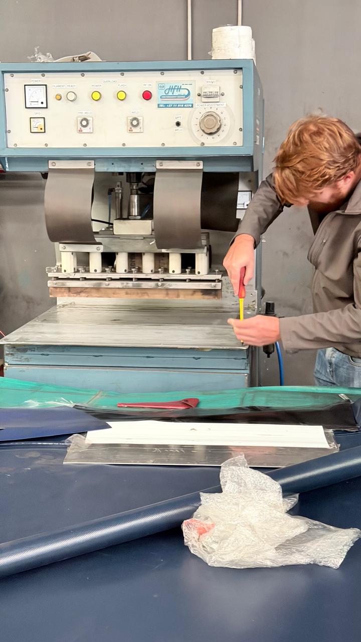
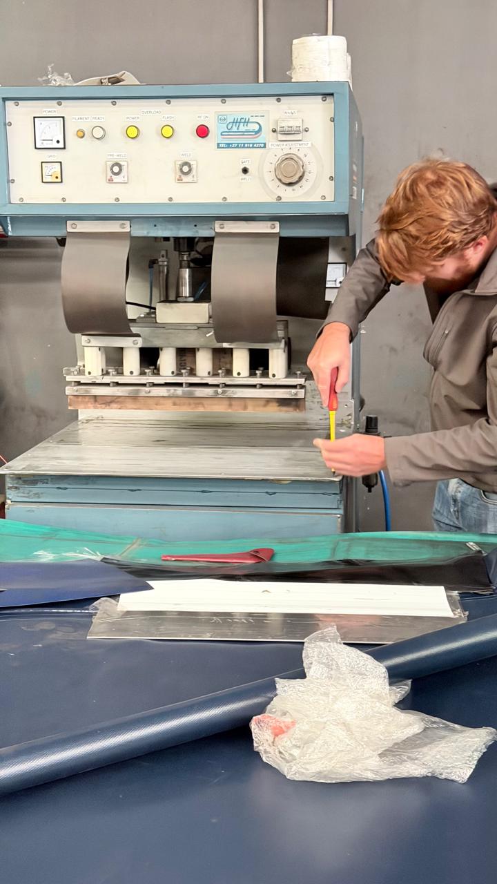
Every workshop eventually runs into the same problem. A machine has a part on it that was made by hand years ago, there is no drawing, no CAD model and no record of who built it. The part is a wear item, so it has to be replaced. The machine is in production, so it cannot be stripped down while somebody stands there with a vernier and a notepad.
We hit exactly this on a welding machine recently. The plate in question was fabricated by artisans. Every hole was drilled by hand and every bend was set by hand. The result works, but the hole pattern is not on a clean grid and the bends are close to square without being perfectly square. That is the signature of hand fabrication, and it means you cannot simply assume a nominal pitch and draw it up from first principles. If you guess, the new plate will not drop onto the existing fixture.
The plate is a consumable. It gets replaced on a cycle, so we needed a repeatable digital pattern that could be sent straight to laser cutting and bending. What we did not need was an hour of production time lost every time somebody wanted a measurement.
The method
We used A0 paper and carpenter's pencils.
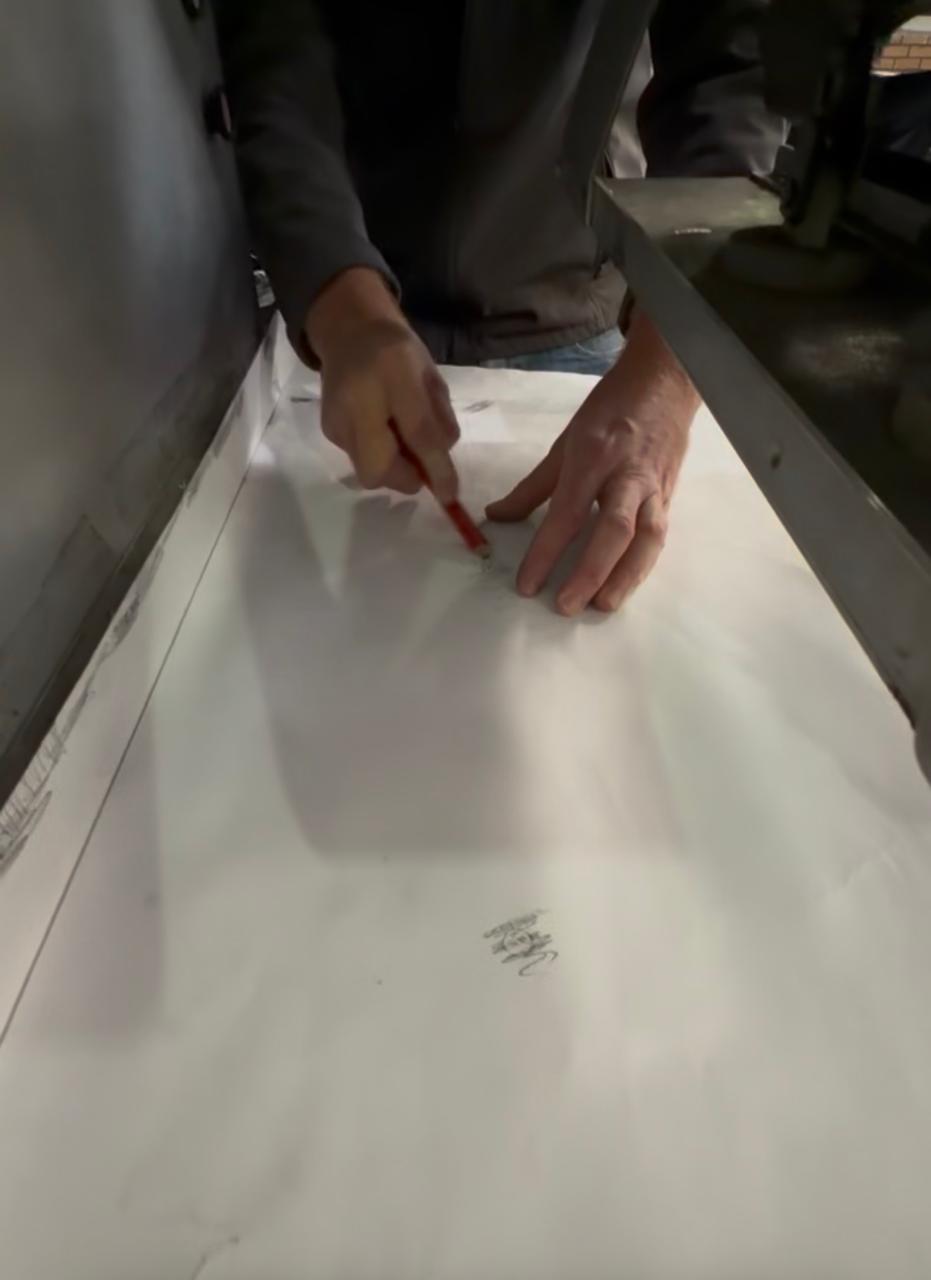
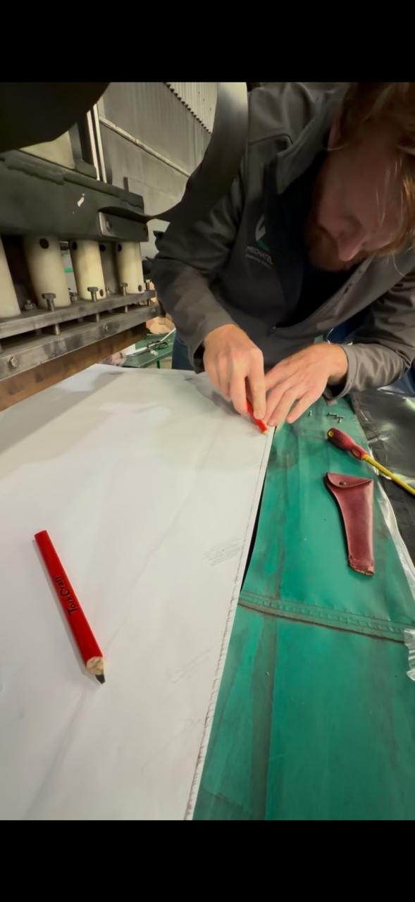
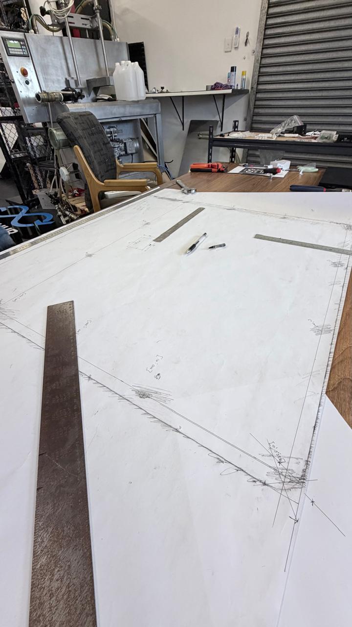
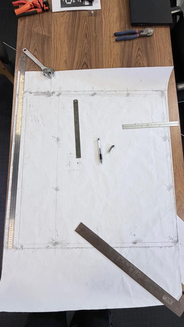
The paper is laid over the plate while the plate is still on the machine. Because the paper is large and flexible, it wraps over the bends and conforms to the shape of the part. All the bends on this plate are right angle bends, which is what makes the technique work cleanly. You then rub the flat side of a carpenter's pencil across the surface. Every edge, every hole and every bend line transfers onto the page as a clear graphite impression.
That impression is the flat pattern. The paper has effectively unfolded the part for you.
Once the rubbing is complete, the paper comes off and the machine goes straight back into production. Total time on the machine is short. The measuring work happens later, back at the office, on a flat table, with proper instruments and no pressure from a production line waiting to restart.
From there the process is ordinary. We measure hole centres, edge distances and bend line positions off the template, build the flat pattern in CAD, apply the correct bend allowances, and release it to laser cutting and bending. The new plate matches the original because the original told us its own dimensions.
Why it matters commercially
The alternative approach is to strip the plate off the machine, take it to a bench, measure it properly and refit it. On this job that is roughly an hour of downtime, and an hour of downtime on a welding line is an hour of no product.
The rubbing technique moves nearly all of that work off the machine and into the office. The machine stops for the time it takes to lay paper down and shade over it, and no longer. Nothing is disassembled. Nothing is disturbed. Nothing has to be reset or re-aligned afterwards.
There is a second benefit that is easy to overlook. Once you have gone to the trouble of building the CAD flat pattern, the part is no longer an undocumented one-off. Every future replacement is a file sent to the laser, not another archaeology exercise on the shop floor.
Practical tips
- Clean the surface first: Grease, weld spatter and scale will all transfer onto the paper and confuse the rubbing. A quick wipe down makes the difference between a clear impression and a smudge.
- Keep the pencil sharp and use the flat: A carpenter's pencil gives you a broad flat edge, which is what produces an even rub. A dull or rounded tip gives vague lines and vague lines become dimensional error later.
- Use two people on large sheets: On an A0 sheet, one person holding the paper flat and steady while the other rubs is far faster and far more accurate than one person trying to do both. Paper that shifts mid rub will ruin the pattern.
- Mark your datum and orientation before you lift the paper: Note which edge is which and which way is up. It is obvious while you are standing at the machine and much less obvious an hour later at a desk.
- Capture the bend lines, not just the holes: The bend positions are what turn the rubbing into a usable flat pattern. Shade across each bend so the transition is visible.
The takeaway
Reverse engineering does not always need a scanner, a CMM or a stripped machine. Sometimes it needs paper, a pencil and a bit of thought about where the work should actually happen.
The principle generalises. Move as much of the job as possible off the running machine and into an environment where you control the conditions. The machine keeps producing, your measurements get better, and the customer does not pay for downtime that was never necessary.